Separating Axis Theorem (SAT)
Published on April 13, 2016Tags: Collisions, MathFirst post! To start things off with a bang, I thought I'd start with a topic that's a favorite of mine: separating axis theorem.
What is it?
Separating Axis Theorem (SAT) is a type of collision detection that can be used in both 2D and 3D, though the complexity in implementation varies. It is based around the principle that if two bodies are NOT colliding, they will be separated on at least one axis, i.e. there will be a gap between them on that axis. To understand what this means, let's define what we mean by a body.
A body for our purposes is some object (a collider) that possesses a position (which we'll say is its center point), an orientation (more on this later), and dimensions, which we'll represent as a vector composed of the width and height values (adding depth in 3D) divided by 2 so that adding them to the center point will reach a corner of the collider. Our body will also have a bunch of surface normals, unit vectors that extend outwards from the body. Technically, any object will have an infinite number of normals, but obviously we can't work with that many so we limit it to one normal per edge in 2D and one per face in 3D. For now, we'll work with a box-shaped collider for ease of use.
2D SAT
Let's start in 2D. Our box collider in 2D is just a square. We have 4 possible normals: top, left, right, and bottom, which we can derive from the corners, aka vertices, of the box. To find the box's corners, we need its center point and dimensions, as well as its orientation. Since we can only rotate around one axis (Z) in 2D, orientation can be represented as a single scalar value, a float. If we rotate our dimensions, adding the new rotated vector to the center point gives us our corners. For example, to compute the top left corner, we do this:
/*
this equates to (dims.x * cos(orientation) - dims.y * sin(orientation)
                ,dims.x * sin(orientation) + dims.y * cos(orientation))
*/
vec2 rotatedDims = rotate(dims,orientation);
//alternatively, tl = center - rotatedDims;
vec2 tl = vec2(center.x - rotatedDims.x, center.y - rotatedDims.y);
You can compute all the other vertices of the bounding box using the rotated dimensions. Then, to compute the normals:
vec2 norm = tl - tr;
norm = vec2(-norm.y, norm.x);
What we did there was we got the edge between the top left and right corners (i.e. the top edge), and rotated it 90 degrees. We guarantee it faces outward from the center of the body by going in clockwise order, where the previous corner subtracts the current one to get an edge facing left. We could go the opposite direction simply by negating x instead of y,
i.e. vec2(norm.y, -norm.x);. I should note that this method of computing normals does not guarantee they are unit length. If that is required, just normalize them by dividing them by their length. This is slow if we recompute them every frame though.
If we're dealing with a more generic case where we can have colliders with any number of sides (and it would behoove you to do so, since it'll save you some code if you want variety in your collider shapes), we can write much more generic versions of these functions, assuming we're working with perfectly uniform colliders of varying shape. However, we're sacrificing some flexibility for simplicity and working with rectangular colliders. Another way we'll be making our code more generic is by replacing the concept of a corner with a vertex. Calling a point a corner implies that it lies at some definite point of a shape, but a vertex is just any point that defines a body. These two terms are synonymous in the context of a box collider, but we'll see later that the distinction becomes important. Here is our example code for keeping our collider's vertex and normal data up-to-date:
//assume verts (and norms) are predefined vec2[4]
void updateVerts() {
    vec2 rotDims = rotate(dims, orientation);
    //top left
    verts[0] = center - rotDims;
    //top right
    verts[1] = vec2(center.x + rotDims.x, center.y - rotDims.y);
    //bottom right
    verts[2] = center + rotDims;
    //bottom left
    verts[3] = vec2(center.x - rotDims.x, center.y + rotDims.y);
}

void updateNorms() {
    vec2 prev = verts[verts.length - 1];
    for(int i = 0; i < verts.length; i++) {
        vec2 norm = prev - verts[i];
        norm = vec2(-norm.y, norm.x);
        norms[i] = norm;
        prev = verts[i];
    }
}
These two functions are each called once per frame (with updateVerts getting called first) and make sure that collider data matches the body's orientation. Fortunately, even though we're recomputing this data every frame the operations involved are all pretty simple, with the exception of the singular rotate().
If we want the collider flexibility we sacrificed for the simplicity of box colliders, a better approach would be to have a predefined list of vertices that define the body and transform them individually and store them in a list that's updated once per frame,
e.g. currVerts[i] = rotate(verts[i], orientation);, but when we're just working with box colliders, this is the more expensive way to do it. This technique is far more relevant when we go into 3D, but for now you can just stick to the regeneration approach.
The Algorithm
We've now laid all the groundwork we need to actually implement SAT. To review, our collider requires up-to-date:
- Position
- Orientation
- Dimensions
- Vertices
- Normals
We'll be using all of these. The other thing to recall is that the Separating Axis Theorem states that if you can find an axis (aka a direction) upon which two objects have separation, they are not colliding. Now, if two objects aren't colliding, there are infinite axes that they are separate on, but we're more interested in a subset of those infinite axes. What we want is a set of axes we can test that, if we don't find a separation on any of them, we know the objects must be colliding. This subset can be said to be the combined set of normals for both colliders. Why can we be certain there is a collision if there is no separation on any of these axes? Simple: if we can't find a side on either object upon which they have separation, by process of elimination they must be colliding. It should be noted that this frame of logic is how it works in 2D; we have to make a few changes in 3D.
As you might imagine from such a general premise, there are many possible ways to implement SAT. Two popular ways to go about it are max-min projection and axis of minimum penetration. We'll talk about the former first, since it's simpler.
Max-Min Projection
Even if you've never heard the term before, you're likely already familiar with the concept of max-min penetration. If you've ever worked with an Axis-Aligned Bounding Box (AABB), where we use a box-shaped collider aligned to the x and y axes with a specific width and height (or the simplified version which does away with the container) then you've used this technique. (we're working with Oriented Bounding Boxes (OBBs), by the way)
Let's start by reviewing AABB checks. We know our collider has an x and y coordinate (which we'll have as the top left instead of the center) and a width and height. To check for a collision between them we do a few simple comparisons:

bool AABBcollision(AABB a, AABB b) {
    //does box A fall within box B?
    bool aCollide = (a.x > b.x && a.x < b.x + b.width) &&
              (a.y > b.y && a.y < b.y + b.height);
    //does box B fall within box A?
    bool bCollide = (b.x > a.x && b.x < a.x + a.width) &&
            (b.y > a.y && b.y < a.y + a.height);
    return aCollide || bCollide;
}
There's actually a simpler way to do this. We can reduce those eight comparisons (two x and y collisions for both cases) to four by checking whether there is NO collision:
bool AABBcollision(AABB a, AABB b) {
    //is there NO collision on the x-axis?
    bool xSeparate = a.x + a.width < b.x ||
             b.x + b.width < a.x;
    //is there NO collision on the y-axis?
    bool ySeparate = a.y + a.height < b.y ||
             b.y + b.height < a.y;
    //a collision only occurs when there is a collision on both x and y
    return !xSeparate && !ySeparate;
}
This is actually our max-min projection check. To explain, first let's define our terms here. The projection of a point onto the x or y axis is simply its x or y coordinate. The minimum and maximum projections on a body for an AABB, therefore, are its minimum and maximum x and y coordinates. The minimum x and y coordinates on a box collider are always on its top left corner (hence why we define them there), while its maximums are on the bottom right corner. (x + width and y + height) We can determine there is no overlap on an axis if either bodies' maximum is less than the other's minimum. With an AABB, we know for a fact that there are only 4 possible directions/axes to check: the positive x and y axes and the negative x and y axes. However, the results for one signed set will be the same as the other; going the opposite direction doesn't change whether or not there is separation along the axis. So we simplify it to just the positive x and y axes, as using the negative ones would require negating our coordinates.
At this point you probably have an idea of how to translate this to our OBB case. Instead of working with the actual x and y axes, we work with our body's "x and y axes." These would be the normals coming out of the body (at default orientation) horizontally and vertically. The question now is: how do we get the projection onto these axes? That's easy: the dot product. The dot product of two vectors A and B gives the projection of vector A onto vector B. We can use this to project any given point onto our axis. However, there is another, less immediately apparent issue. The top-left and bottom-right vertices are no longer guaranteed to have the minimum and maximum projections now that we're not locked to the x and y axes. This means we have to find the maximum and minimum projections ourselves.
//this is an OBB method
vector<float> findMaxMin(vec2 axis) {
    vector<float> maxMin;//[0] is the max, [1] is the min
    //we start with the first vertex's projection as a baseline
    maxMin[0] = dot(verts[0], axis);
    maxMin[1] = maxMin[0];
    for(int i = 1; i < verts.length; i++) {
        float proj = dot(verts[i], axis);
        //we found a new maximum
        if(proj > maxMin[0])
            maxMin[0] = proj;
        //we found a new minimum
        else if(proj < maxMin[1])
            maxMin[1] = proj;
    }
    return maxMin;
}
We iterate over every vertex in the collider and project it onto our axis. If the projection is greater than our maximum or smaller than our minimum, we replace that value. At the end, we return our final max and min values. We've now got all the same information we needed to do our AABB check.
Where AABBs only need to worry about overlap on the x and y axes, we have a whole list of normals to check. (though for box colliders this amounts to two) We can combine our lists of normals from both colliders and call this the "axes" list, and then iterate over that, checking is there is NO overlap on any of them. At the end, if we got through all the axes, we know there must be a collision.
 these are just some of the axes; we see one of them has separation
bool intersects(OBB a, OBB b) {
    //circle collision optimization
    vec2 d = a.pos - b.pos;
    float distSq = dot(d, d);
    float r = max(a.width, a.height) + max(b.width, b.height)
    if(distSq > r * r)
        return false;

    //SAT
    //combineVectors() is not a real function
    vector<vec2> axes = combineVectors(a.norms, b.norms);
    for(int i = 0; i < axes.size(); i++) {
        vec2 axis = axes[i];
        vector<float> aProj = a.findMaxMin(axis);
        vector<float> bProj = b.findMaxMin(axis);

        //we found a separating axis boys
        if(aProj[0] < bProj[1] || bProj[0] < aProj[1])
            return false;
    }
    //no separating axis was found, so there must be a collision
    return true;
}
The entire function comes in at about 20 lines, even without cutting the fat. Very nice.
You'll notice we do a circle collision check before doing SAT. This is because it's much faster to use a circle collision check to determine if there's no collision then if we go through all of SAT; this relates to the concept of "broad-phase" vs. "narrow-phase" collision detection. We do simple broad-phase collision checks, like circles and AABB, to cull any obvious non-collisions, and then use narrow-phase to get precise collision information. Typically the broad phase also includes spatial partitioning, but we won't touch on that here. You'll also notice we use the highest dimension the collider has as a radius. This ensures the object is covered by the circle, but also means that this approach becomes less effective at culling collisions the more exaggerated any one dimension becomes compared to the others; when this is the case, AABBs become more effective for broad phase checks.
Axis of Minimum Penetration
Max-min projection was fun, but now let's talk about the concept of the axis of minimum penetration. We draw several concepts in this method from another type of collision detection called GJK, but add in some SAT flavor for the best of both worlds. This is also a much newer technique than max-min projection in the context of SAT.
To give an overview of the principles here, we first have to talk about the concept of a support point. A body's support point along an axis is the vertex with the greatest positive projection along that axis. It's very straightforward in code:
vec3 getSupportPoint(vec3 axis) {
    vec3 support = verts[0];
    float maxProj = dot(support, axis);
    for(int i = 1; i < verts.length; i++) {
        float proj = dot(verts[i], axis);
        if(proj > maxProj) {
            support = verts[i];
            maxProj = proj;
        }
    }
    return support;
}
Support points don't do much for us on their own. It's only when we use them in the context of the algorithm that they become useful.
The thought process behind this method is pretty ingenious. On our colliders, we have a series of sides. Each side is defined by two points, and from these two points we generate a normal. We can also define these sides, or edges, as a point and a normal, which defines a plane aligned with the edge as well. Now, if we look at how collision works, there must be an overlap between the two bodies. This overlap is, by nature, closest to one edge of one of the bodies and the other body penetrates this edge with some specified depth. So we know that for any given collision, we have a collision edge plane, which can be defined as a vertex (V) and a normal (N), and a penetration depth.
The key thing is finding that collision plane. In any given collision, we may have multiple edges overlapping the other body, so we need to know how to distinguish which edge plane is the correct one. What we define as the "correct" collision plane is the one that requires the least positional correction to resolve the collision, which we can more simply define as the one with the smallest penetration depth. The normal of this plane is what we call the axis of minimum penetration.
To find which edge normal has the least penetration, we have to go through each side's normals and vertices. But how do we determine how much the other body is penetrating along that axis? Since we know that vertices will always represent a point on the edge of the body, the point that penetrates the other body the most MUST be a vertex. That means we want to find the vertex furthest in the direction of penetration of the side we test; in other words, we want the support point for the normal, but in the opposite direction, which we can achieve by negating the normal. To get the projection of the support point (S) onto the plane, all we have to do is project the vector between the plane and the support point (S - V) onto the normal.

We then determine if that projection is the greatest we've found so far. That may seem counter-intuitive, but think about it this way: when the projection is positive, it means the support point is actually in front of the plane, so there's no collision. (this is where we identify separating axes) We know that the max penetration we could possibly have is the maximum value of a float, which is FLT_MAX in C/C++ and is located in float.h. Because we know that the projection is negative if there's overlap, our maximum penetration is -FLT_MAX. Any value "less" than that must either be positive, where there is no overlap, or it will be negative, in which case it will approach a minimum penetration of zero. Therefore, the axis of minimum penetration is the one with a negative projection closest to zero.
However, this is only a possible axis of minimum penetration. The axis we get only applies for one body; therefore we must get each body's axis of minimum penetration and compare them. If either has penetration > 0, we know there is no collision.
To compare them, we need the projection value. To actually correct the collision, which we'll probably want to do, we need the axis. It would also probably help to know which body actually had the axis, and what the other body it collided with was. Since we need so many values, we introduce the concept of a manifold, a struct that contains collision data. It looks like this:
struct Manifold {
    OBB* originator = null_ptr;
    OBB* other = null_ptr;
    float pen = -FLT_MAX;
    vec3 axis;
};
This will be our container for all the data we get from our axis of minimum penetration function, and we will ultimately return it so we can handle the collision later.
Manifold axisMinPen(OBB* other) {
    Manifold m;
    m.originator = this; m.other = other;
    //end early if we ever observe separation
    for(int i = 0; m.pen < 0 && i < norms.length; i++) {
        vec3 norm = norms[i];
        vec3 support = other->getSupportPoint(-norm);
        //because of how we generate normals,
        //this vert will always be on the corresponding edge
        //THIS DOES NOT NECESSARILY HOLD TRUE LATER
        vec3 vert = verts[i];

        float proj = dot(norm, support - vert);
        if(proj > m.pen) {
            m.pen = proj;
            m.axis = norm;
        }
    }
    return m;
}

//we know there was no collision if the originator is null_ptr
Manifold intersects(OBB* a, OBB* b) {
    Manifold m;

    //circle collision optimization again
    vec2 d = a.pos - b.pos;
    float distSq = dot(d, d);
    if(distSq > max(a.width, a.height) + max(b.width, b.height))
        return false;

    //axis min pen on A
    Manifold aMin = a.axisMinPen(b);
    if(aMin.pen > 0)
        return m;

    //axis min pen on B
    Manifold bMin = b.axisMinPen(a);
    if(bMin.pen > 0)
        return m;

    //get axis of true min pen
    m = (aMin.pen > bMin.pen) ? aMin : bMin;
    return m;
}
You'll notice we still have the circle collision optimization. It's still faster than the SAT checks, so we still have it. The general flow of this version is much simpler. It's as simple as finding one collider's axis of minimum penetration with respect to the other, finding the other's with respect to the first, and finally returning the one with less penetration. We finish early if we find that either collider's axis of minimum penetration is a separating axis. The math is a bit more complex than max-min projection, but it's still pretty simple conceptually.
Which One Should I Use?
If you want to generate manifolds, it's simplest to use axis of minimum penetration. For this reason, we'll be sticking with this version in future posts. However, I actually prefer max-min penetration if I just need to know if there's been a collision; I think it's much more aesthetically pleasing. Our input is all the normals of the colliders we're comparing, and we just iterate over that input. It's a very pure-functional type of algorithm, and I appreciate its elegance. To reiterate though, if you need collision data, which you almost always will, use axis of minimum penetration.
Extra Notes
We mentioned earlier that using the set of both colliders' normals to determine lack of a separating axis only works in 2D. There are other considerations we must make, however, not only in 2D but also in 3D. One important thing is knowing where the center of the body is in relation to the points on the body. Like most transformation-geared systems, we try to orient ourselves around the origin. In the case this doesn't happen though, we need to make allowances for it or the algorithm will break. In our implementation where vertices and normals are generated per-frame, we always assume the center of the collider is its position; this is not always the case, and becomes especially important in the vertex list implementation, which we'll soon see.
Another thing to know is that SAT only works when both bodies are convex. What does that mean? Basically, if we can't draw a line between any two points on a body that ever exits the body's boundaries, the shape is convex. Here is a visual example:

If a body is concave, i.e. some line can be drawn that DOES go outside the body, SAT no longer works. In this case, we either must use some other algorithm (though I don't know of any that work with concave bodies that are particularly efficient) or convert the concave body into a set of convex bodies, like so:
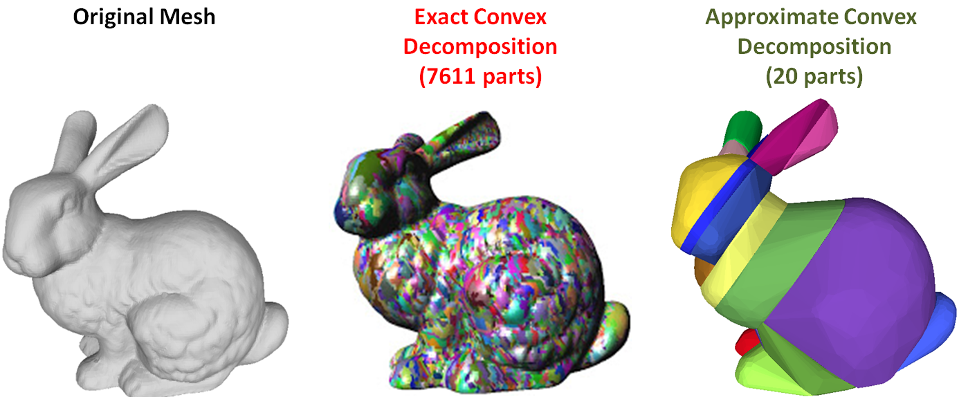
This can be done manually or with the aid of some algorithm, such as Approximate Convex Decomposition. The important thing to remember is to always make sure your colliders are convex. In 2D, this is generally obvious, but be careful in 3D, as something that may seem convex at first glance may not actually be.
Next time, we'll move onto SAT in 3D. That's where things start to get hairy, but also more interesting.